Thermostats / MAXTHERMO MC-5x38 PID Temperature Controllers OPERATION MANUAL
MAXTHERMO MC-5x38 PID Temperature Controllers OPERATION MANUAL

Display Block and Indicator Lamps
| PV = Measured value display |
| SV = Set value display |
| AL1 = Alarm 1 output indicator |
| AL2 = Alarm 2 lamp |
| AL3 = Alarm 3 lamp |
| OUT1 = Control output 1 lamp |
| OUT2 = Control output 2 lamp |
| AT = Auto-tune lamp |
| MAIN = Manual mode indicator |
| 10% - 100% = Adjustable output value display |
| PRG = Program mode lamp |
| RP = Ramp mode lamp (program mode only) |
| SK = Soak mode indicator (program mode only) |
Control Keys
 Function and Settings key Function and Settings key |
 |
 Down key Down key |
 Up key Up key |
| Press and hold for 3 seconds until SV flashes = used to return to the initial window |
| Press and hold for 3 seconds in the level selection window = Used to call up the lock function |
| Press for 3 sec. while in the initial pv/sv window = used to stop the output, and the SV window will display "HOLD", press for 3 seconds again to restore the output (This function is only available when OUTM 1 or 2 is selected) |
| Press for 3 seconds in the initial pv/sv window = Used to call up level selection |
| Press and hold for 3 seconds in the level selection window = used to enter each level. |
Control Buttons (program mode only).
| These keys only operate in the initial PV/SV window. |
| 3 seconds | PRG lights up, RP or SK flashes. The active segment indicator lights up |
| 3 seconds Pause | PRG, RP and SK light up. The active segment lamp lights up |
| + | Go to the next segment, press |
| + | Turn off all lamps that were used for program mode, press |
See arrow  |
The window checks the display after power-up.
Unit (C)
K2 input 0~400 SV display

Parameter Menu Structure.
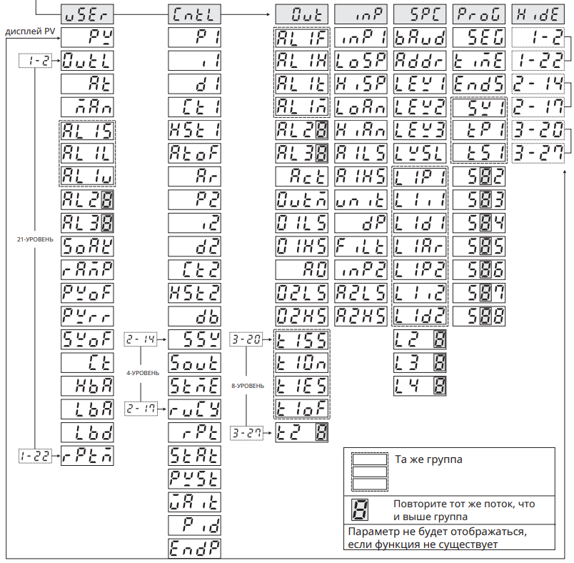
Programmable Device Parameters
| Parameter | Description | Range | Factory Settings |
 | Process value | LoSP~HiSP | - |
 | Set value | LoSP~HiSP | 0.0 |

 | 0.0~100.0% | 0.0 |
 | Auto-tune No-Yes | No |
 | Man1 = power failure memory Man2 = no memory No = no | No |
 | 0~200 | 10.0 |
 | 0~200 | 10.0 |
 | 0~200 | 10.0 |
 AL2S / AL3S Operating functions, see descriptions above. AL2S / AL3S Operating functions, see descriptions above. |
 | Only performed when ALM1 is set to 8 or 9 | 0.00~99.59 (hm) | 0.00 |
 | Ramp | 0.0~200.0/m | 0.0 |
 | PV offset | -200~200 | 0.0 |
 | PV ratio | 0.001~9.999 PV*Pvrr  | 1.000 |
 | Offset | -200~200 | 0.0 |
 | Current transformer monitor | 0.0~100.0A | - |
 | Heater break alarm time | 0.1~100.0 | 0.1 |
 | Control loop break alarm time | 0.1~200.0 min | 8.0 |
 | LBA dead band | 0.0~200.0 | 0.0 |
 | Repeat time control | 1~1000 |

 | Output 1 proportional band | 0.0~3000 | 30.0 |
 | Output 1 integral time | 0~3600 | 240 |
 | Output 1 derivative time | 0~900 | 60 |
 | Output 1 cycle time | 0~150 | 15 |
 | Output 1 hysteresis | 0.0~200.0 | 0.0 |
 | At offset | -200~200 | 0.0 |
 | Anti-reset windup | 0~100.0% SV-P1 x Ar | 100.0 |
 | Output 2 proportional band | 0.0~3000 | 30.0 |
 | Output 2 integral time | 0~3600 | 240 |
 | Output 2 derivative time | 0~900 | 60 |
 | Output 2 cycle time | 0~150 | 15 |
 | Output 2 hysteresis | 0.0~ 200.0 | 0.0 |
 | Dead band/overlap | 200.0~ 200.0 100% 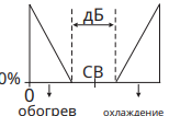 | 0.0 |
 | Soft-start set value | 0.0~200.0 | 120.0 |
 | Soft-start output percentage | 0.0~100.0% | 30.0 |
 | Soft-start failure time | 0~10 min | 10.0 |
 | Motor valve cycle time | 1~150 | 5 |
 | Program execution time | 1~1000 | 1 |
 | Start mode selection | Cold = manual rSET=start after power-on Heat = start from power-failure memory | Cold |
 | Start point selection | RSEt = start at 0 Pv = start at PV | rSEt |
 | Wait value in program | 0.0~200.0 | 0.0 |
 | PID/PID level selection | Pid = PID Lpid = linear PID level | PID |
 | Selects control when program has ended | Proceed = Continue StoP = single program only | StoP |
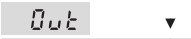
 | Alarm 1 action function | 0~12 | 1 |
 | Alarm 1 hysteresis | 0.0~200.0 | 0.0 |
 | Alarm 1 in program mode | 0.00~99.59 (m) | 0.00 |
 | Alarm 1 special mode selection | 0 |

AL3F Alarm 3 action function 0~11
AL3M Alarm 3 special mode selection
 | Control action selection | COOLING / HEATING | Heating |
 | Output mode selection | 1 | |
 | Output 1 low scale | 0.0~100.0% | 17.6 |
 | Output 1 high scale | 0.0~100.0% | 96.0 |
 | Analog output selection | Pv=transmit PV Sv= transmit SV dEv=transmit (PV-SV) Mv=transmit output signal percentage | PV |
 | Output 2 low scale | 0.0~100.0% | 17.6 |
 | Output 2 high scale | 0.0~100.0% | 96.0 |
 | Time signal 1 start segment setting | 1~8 | 1 |
 | Time signal 1 on-time setting | 0.00~99.59 (h/m) | 0.01 |
 | Time signal 1 end segment setting | 1~8 | 1 |
 | Time signal 1 off-time setting | 0.00~99.59 (h/m) | 0.01 |
 |
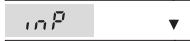
 | Input 1 selection | K2 | |
 | Set point lower limit | LoSP~HiSP | 0.0 |
 | Set point upper limit | LoSP~HiSP | 400.0 |
 | Analog input low range | -1999~9999 | 0.0 |
 | Analog input high range | -1999~9999 | 100.0 |
 | Analog input 1 low scale | 0~FFFF | |
 | Analog input 1 high scale | 0~FFFF | |
 | Unit selection | C/F | C |
 | Decimal point | 0/0.0/0.00/0.000 | 0.0 |
 | Digital filter | 0.001~1.000 | 0.900 |
 | Input 2 selection | No = no function Ct = used for heater break alarm inP2 Input 2 selection rmSV= used for remote SV | No |
 | Analog input 2 low scale | 0~FFFF | |
 | Analog input 2 high scale | 0~FFFF |

 | Baud rate | 2.4K / 4.8K / 9.6K 19.2K / 38.4K | 9.6 K |
 | Address | 0~31 | 0 |
 | PID range (effective only when PID level is selected) | LoSP~HiSP | 400 |
 | PID range (effective only when PID level is selected) | LoSP~HiSP | 400 |
 | PID range (effective only when PID level is selected) | LoSP~HiSP | 400 |
 | LEYS selection | 1~4 | 1 |
 | Output 1 proportional band for level 1 | 0.0~3000 | 30.0 |
 | Output 1 integral time for level 1 | 0~3600 | 240 |
 | Output 1 derivative time for level 1 | 0~900 | 60 |
 | Anti-reset windup for level 1 | 0.0~100.0% | 100.0 |
 | Output 2 proportional band for level 1 | 0.0~3000 | 30.0 |
 | Output 2 integral time for level 1 | 0~3600 | 240 |
 | Output 2 derivative time for level 1 | 0~900 | 60 |
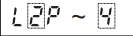 Same as level 1 Same as level 1 |

 | Program segment monitor | 1~8 | |
 | Program countdown monitor | ||
 | Program end segment setting | 1~8 | 1 |
 | SV in segment 1 | LoSP~HiSP | 100 |
 | Program time in segment 1 | 0.00~99.59 (h/m) | 0.00 |
 | Soak time in segment 1 | 0.00~99.59 (h/m) | 0.00 |
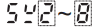 Same as segment 1 Same as segment 1 |
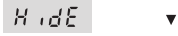
 | Parameter shows relative to this position | no~t2of | - |
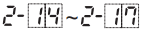 | Parameter shows relative to this position | no~t2of | - |
 | Parameter shows relative to this position | no~t2of | - |
Mounting Procedures.
